
Motivation
This post is written to show an implementation of Convolutional Neural Networks (CNNs) using numpy. I have made a similar post earlier but that was more focused on explaining what convolution in general and CNNs in particular are whereas in this post the focus will also be more on implementing them efficiently in numpy by using vectorization.
It is worth pointing out that compared to packages like tensorflow, pytorch etc., using numpy does not offer any benefits in speed in general. In fact if one includes development time, it is most likely slower. The idea of the post is not to advertise the use of numpy for speed but to share the author’s experience of rebuilding the wheel. While the same is often derided, or demonized even, it is only with rebuilding a few wheels that one is able to to invent new machinery. Not to mention, sometime rebuilding the wheel is just plain fun!
We will focus solely on the CNN part of it and the other related aspects like activation function and maxpooling etc will not discussed here as they can be implemented as separate layers acting on the output of the CNN layer. However, we do discuss padding and stride which are inherent to the convolution process.
The code for this post can be found in the repository with most of the code contained in the file CNN.py
Since the goal of the post is to show how to make an efficient implementation of CNNs in numpy, I will not provide all the code in this post but instead explain the idea of what is being done with lots of visualization and only the relevant code. All the code can of course be found in the aforementioned repository.
Convolutional Neural Networks
Forward Pass
We will work on 2 dimensional images with multiple channels. For actual images the number of channels is either 1 for monochrome images or 3 (Red/Green/Blue or RGB in short) for colored images. However, a CNN could itself act on the output of a previous CNN and then the meaning of channels is the output of different filters of the previous layer and so the number of channels can be any positive integer. Nevertheless, below we concretely talk about 3 channels while coloring them RGB to help visualize the process.
The convolution layer has the filter weights as learnable parameters and two hyperparameters – the stride and the padding. These are denoted below as
$$
W_{ijkl},s,p
$$
which are a 4 dimensional tensor and two scalars respectively. The first two dimensions of the weights run over the row and column of the convolutional filter whereas the third one runs over the input channels and the fourth one over the output channels. Note that the the stride and padding can be different for each dimension of the image but for notational simplicity we keep them the same below (although in the actual code allows for different values).
We denote the input of a convolution layer by
$$
l^0_{I,i,j,k}
$$
where the indices are the minibatch, the row, the column and the channel respectively. The output is similarly denoted by
$$
l^1_{I,i,j,l}
$$
However, note that except for the minibatch index, the others may have a different range than that of the input ones. This means that the output image sizes and number of channels may be different.
The notion of padding comes from embedding this image in a (possibly) bigger 0-padded array
$$
\tilde l^0_{I,P+i,P+j,k}=l^0_{I,i,j,k}
$$
where \(P\) is the padding. The convolution operation is defined as
$$
l^1_{I,i,j,l} = \sum_{\alpha,\beta,k} \tilde l^0_{I,si+\alpha,sj+\beta,k} W_{\alpha,\beta,k,l}
$$
where \(s\) is the stride.
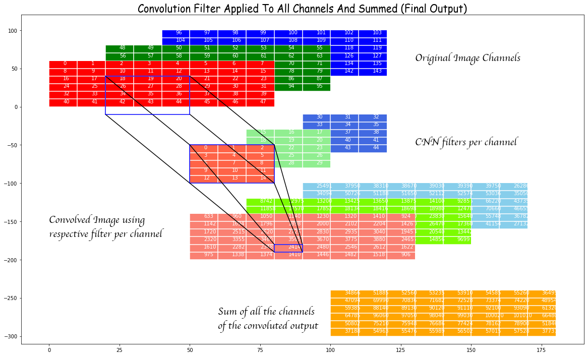
In order to understand the above, we visualize this process by taking an “image” of size \(6 \times 8\) with three channels where we fill in the values sequentially. So the red channel has its first row from 0 to 7, the second row from 8 to 15 and so on till the 6th row going up to 47. The green channel then starts from 48 and fills in the same way.
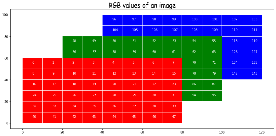
In the above we plot the channels along the depth direction.
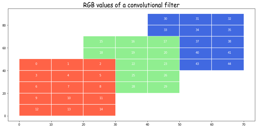
We make a “filter” as having the same structure but a different size. Specifically we take \(5 \times 3\) size filters. Note that while there are three filters here, one for each input channel, this set will produces just one channel of output. For each channel of the output we will need a separate copy of such three filters.
Now we consider the effect of the red filter on the red channel. Before doing that take another look at the expressions for convolutions from above and try to understand what is happening.
In the example in the image below we have taken a padding of 2 in the y-direction and 1 in the x-direction. This means the original image is embedded in the center of a 0-padded array of a bigger size by 4 in the y-direction and 2 in the x-direction. This ensures that the output of convolution is the same size as the input (in the absence of a stride) but we do not have to do that. Padding can be small or perversely bigger.
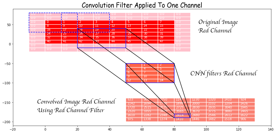
Now look at the effect of convolution of the red filter on the part of the (larger embedded) image in the box starting at (4,3) and of the same size as the filter that is drawn in solid blue. Each element of the window is multiplied by the corresponding element of the filter and the result is then summed. Note that this involves a row of zero-padded values. This sum is the (4,3) rd element of the convolution of the red channel. If we had not zero-paded we could not even have this entry and the output would be limited to those values that come from convolution filters fitting completely inside the original (non zero-padded) image.
Let’s also look at the stride. The effect of the stride can be seen from the theoretical expression. A stride of 1 is the default and its result is shown above. However, if we were to choose a stride of 2, for instance, then the windows used would be like the dashed-blue windows and we see that they are moved in steps of 2.
The final ouput of one filter of 3 channels is given by summing the convolution on the three channels as shown below.
Backpropagation
The derivative of the loss with respect to the weights is given by
\frac{\partial L}{\partial W_{\alpha,\beta,k,m}}=\sum_{I,i,j} \frac{\partial L}{\partial l^1_{I,i,j,m}} \tilde l^0_{I,si+\alpha,sj+\beta,k}
$$
\frac{\partial L}{\partial l^0_{I,p,q,l}} = \sum_{\alpha,\beta,m} \left(\frac{\partial L}{\partial l^1} \right)_{I,\frac{p+P-\alpha}{s} , \frac{q+P-\beta}{s},m} W_{\alpha,\beta,l,m} \\
= \sum_{\alpha,\beta,m} \left(\frac{\partial L}{\partial l^1} \right)_{I,\frac{p+P-K+1+\alpha}{s} , \frac{q+P-K+1+\beta}{s},m} \tilde W_{\alpha,\beta,m,l}
$$
\tilde W_{\alpha,\beta,m,l} = W_{K-\alpha, K-\beta,l,m}
$$
and \(K\) is the filter size. All these can be computed using simple algebra and the chain rule of calculus.
We observe that the derivative of the loss with respect to the input layer is just a convolution of the error with respect to \(\frac{\partial L}{\partial l^1}\) with a filter that has the indices along the first two directions reversed.
This observation tells us that we can reuse our code for convolution but we still need to massage the data \(\frac{\partial L}{\partial l^1}\) before we do that. We can first embed the error with respect to the output in an array
$$
z_{I,si,sj,m}=\left(\frac{\partial L}{\partial l^1} \right)_{I,i,j,m}
$$
Depending on the sign of \(P-K+1\) either a part of z is embedded in a right zero-padded array y or z is embedded in a left and right zero-padded y. The reasoning for this is not easy to explain and what I had to do was carefully consider all possibilities of padding sizes and work out the right logic. To be sure a padding size of more than half the filter size seems perverse, but the logic has to be worked out to ensure the code doesn’t break if for nothing else. If the reader finds an easy explanation I would be happy to receive the same and update this post. The code for this part is given below.
def _prepare_back(self,der_y):
    mb, n1, n2, _ = self.prev_layer.shape
    ch = der_y.shape[3]

    m1 = max(self.stride_1 * der_y.shape[1], n1)
    m2 = max(self.stride_2 * der_y.shape[2], n2)

    z = np.zeros(shape=(mb, m1, m2, ch))
    y = np.zeros(shape=(
    mb, m1 + self.filter_size_1 - 1, m2 + self.filter_size_2 - 1, ch))

    z[:,
    :self.stride_1 * der_y.shape[1]:self.stride_1,
    :self.stride_2 * der_y.shape[2]:self.stride_2
    ] = der_y

    p1_left = self.padding_1 + 1 - self.filter_size_1
    p2_left = self.padding_2 + 1 - self.filter_size_2

    # i1,i2 are the start positions in z and iy1,iy2 are the start
    # positions in y
    i1 = i2 = iy1 = iy2 = 0

    if p1_left > 0:
        i1 = p1_left
    else:
        iy1 = -p1_left

    if p2_left > 0:
        i2 = p2_left
    else:
        iy2 = -p2_left

    # size of array taken from x
    f1 = z.shape[1] - i1
    f2 = z.shape[2] - i2

    y[:,
    iy1:iy1 + f1,
    iy2:iy2 + f2
    ] = z[:, i1:, i2:, :]
    return y
Finally, we have
$$
\frac{\partial L}{\partial l^0_{I,p,q,l}}=\sum_{\alpha,\beta,m} y_{I,p+\alpha,q+\beta,m} \tilde W_{\alpha,\beta,m,l}
$$
which is just a simple convolution.
An efficient numpy implementation
This is all very well but implemented naively in the way described above, the process is very slow. This is because there are several loops:
(i) moving a channel specific filter all over a channel (the actual convolution),
(ii) looping over the input channels,
(iii) looping over the output channels.
(iv) looping over the minibatch
Implemented cleverly the code can use not only numpy vectorization but also use the Dense Layer one may have already written (you will find an implementation in the repository mentioned above). While thinking about how to do this I came across a post by Sylvain Glugger where he does something similar and my ideas are inspired by the same. However, there are two differences (i) for his analysis the channel index is the second one, right after minibatch, and the standard image format keeps it as the last one and that is how I have implemented my code and (ii) my implementation of backpropagation is different. To be honest I could not follow his implementation and I (obviously) think mine is cleaner.
Let’s look at the expression for convolution again
$$
l^1_{I,i,j,l} = \sum_{\alpha,\beta,k} \tilde l^0_{I,si+\alpha,sj+\beta,k} W_{\alpha,\beta,k,l}
$$
We see that we can collapse the indices \(\alpha,\beta,k\) of the filter \(W\) into one index \(\mu = \alpha * f_2 * c + \beta * c + k\) where \(f_2\) is the range of index \(\beta\) and \(c\) is the number of channels. In numpy this is accomplished simply by
W.reshape(-1,W.shape[-1])
We need to correspondingly build a new tensor with the elements that are to be multiplied by these elements of the reshaped \(W\). To be sure this is an involved process and the output will have redundancies but it will allow speed up and what’s more, looking at the expression
\begin{equation}
l^1_{I,i,j,m} = \sum_\mu \bar l^0_{I,i,j,\mu} W_{\mu,m}
\label{eq:eff_conv}
\end{equation}
we see that it is now simply a dense layer and we can use the same for the forward pass and the updating of weights during the backpropagation. The backpropagation to find the derivative of loss with respect to \(l^0\) is something that we will address shortly.
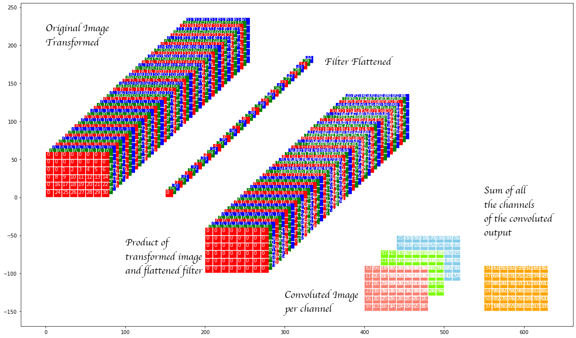
The procedure to obtained \(\bar l^0\) from \(\tilde l^0\) is straightforward and is best explained by the code that is given below. However, let us first visualize what is happening.
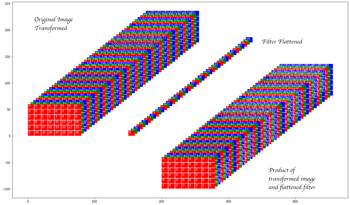
In the image above the original image transformed consists of the elements of the zero padded image rearranged (with duplication) so that each panel (the panels are laid out in the depth direction) contains all the elements that are to be multiplied by on element of the convolution filter. The convolution filter itself is raveled out in the depth direction (and we refer to it as the flattened filter in the image above). The product of these two are shown next.
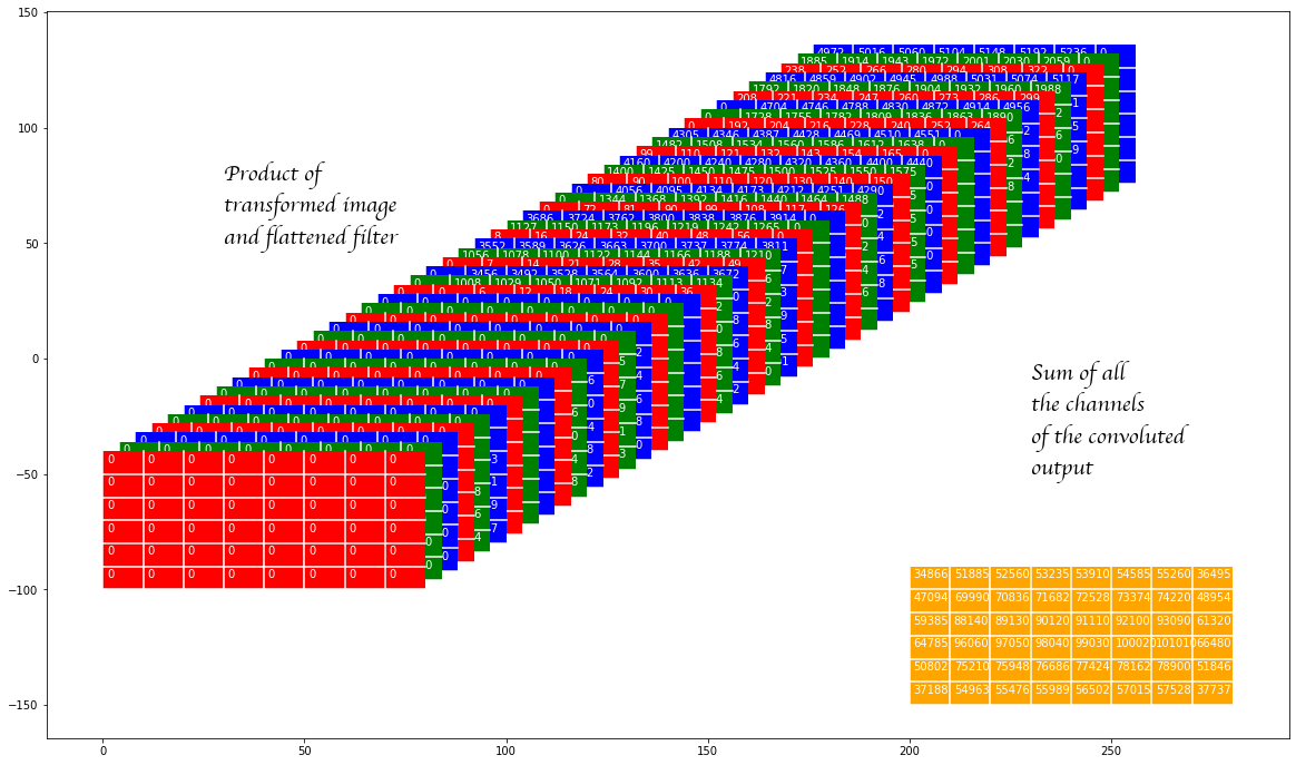
The product of transformed image and the flattened filter is shown again and then we show the sum of all these panels. One can verify that the results are the same.
The code to get the aforementioned transformed image from the zero padded image is given below and this is the main point of this post. Again, the code is part of the CNN layer and hence the reference to ‘self’ but the the meaning should be clear.
def _take(self, y, stride=(1, 1)):

    stride_1, stride_2 = stride
    mb, en1, en2, ch = y.shape

    # Till we discuss the minibatch index, all comments are for the first
    # image

    # Make a 2d array of indices of the top-left edges of the windows
    # from which to take elements. These are to be the indices on the
    # first channel. This makes the indices the top-left-back end of the
    # cuboid to be taken
    s1 = np.arange(0, en1 - self.filter_size_1 + 1, stride_1)
    s2 = np.arange(0, en2 - self.filter_size_2 + 1, stride_2)
    start_idx = (s1[:, None] * en2 * ch + s2[None, :] * ch)

    # Make a grid of elements to be taken in the entire cuboid whose
    # top-left-back indices we have taken above. This is done only for
    # the first of the above cuboids in mind.
    # Note the cuboid elements are flattened and will now be along the
    # 4th direction of the output
    g1 = np.arange(self.filter_size_1)
    g2 = np.arange(self.filter_size_2)
    g3 = np.arange(ch)
    grid = (g1[:, None, None] * en2 * ch + g2[None, :, None] *
            ch + g3[None, None, :]).ravel()

    # Combine the above two to make a 3d array which corresponds to just
    # the first image in a minibatch.
    grid_to_take = start_idx[:, :, None] + grid[None, None, :]

    # Make and index for the starting entry in every image in a minibatch
    batch = np.array(range(0, mb)) * ch * en1 * en2

    # This is the final result
    res = y.take(batch[:, None, None, None] + grid_to_take[None, :, :, :])
    return res
The same code can be used in on the prepared \( \frac{\partial L}{\partial l^1}\) (see code above) to give a corresponding transformed version to perform the convolution for the backpropagation.
The remaining code is pretty straightforward and can be found in the repository mentioned at the beginning of the post.